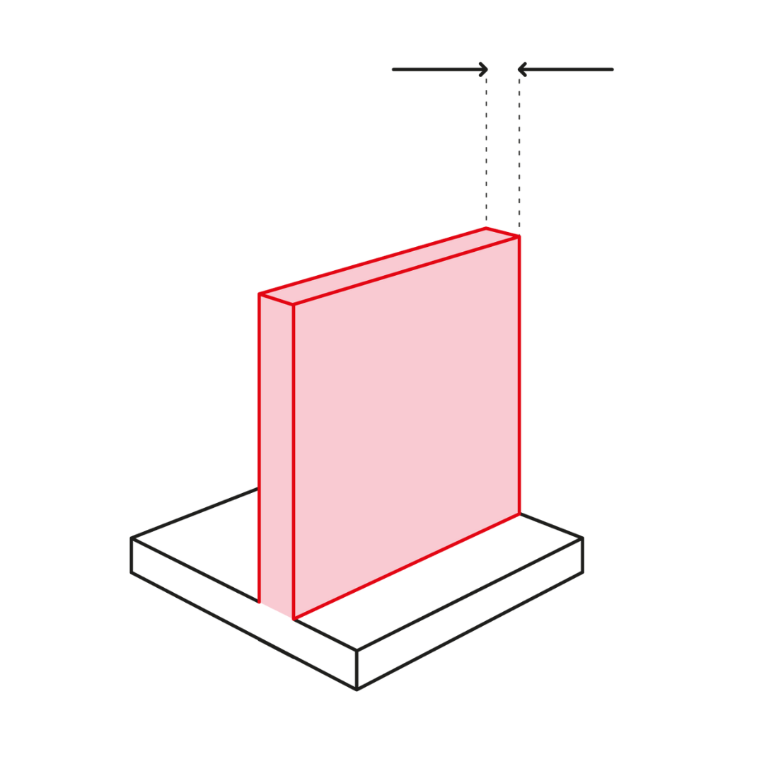
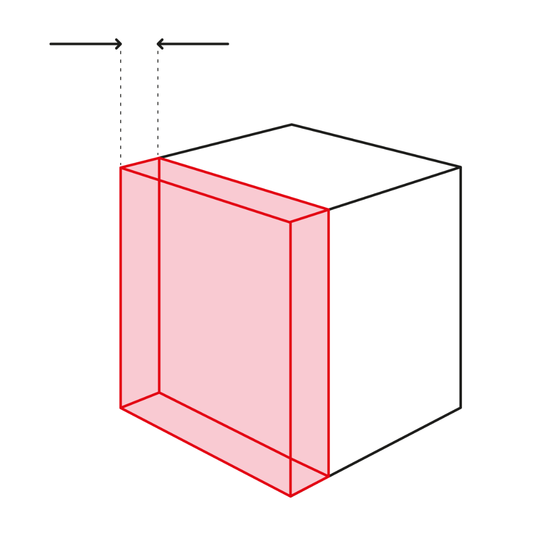
Wall thickness
Regardless of printing orientation, 0,8mm is recommended minimum wall thickness. Depending to area volume of the thin wall and printing orientation we can go down to 0,3mm but it need to be discussed with our engineers. If the wall thickness in over 5mm, lightened stucture is worth of considering.
With PA2210FR to achieve the fire rating UL94 V-0, minimum wall thickness 3mm is required. With PA11 ESD to achieve a sufficent electrically conductive properties, 2mm wall thickness is recommended.
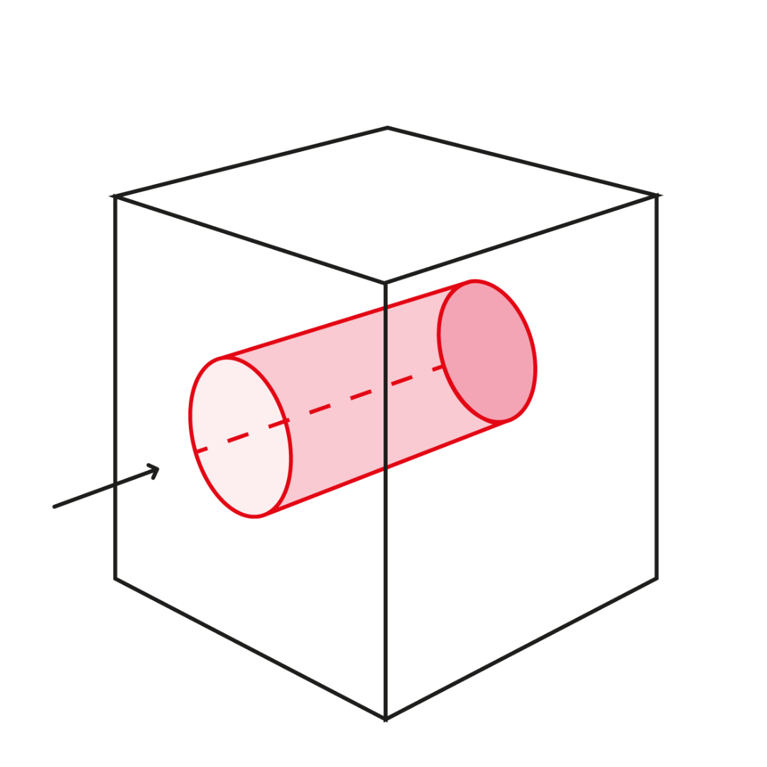
Hole and channel size
At printing phase 1mm hole diameter is recommended minimum to achieve reliable reproducibility. With smaller holes need to discuss more with our engineers. In case of end-product manufacturing over 1.5mm diameter for holes is recommended to make sure that holes are always clear after automated cleaning phase (ball blasting)
With internal channels (with turns) we recommend to use at least 3mm diameter. Cleanability of parts is something to need to pay attention and discussion with our engineers is desirable. Sharps turns of channels should be avoided.
Text
Identification numbers and information is sensible and cost effective to integrate into parts as texts and symbols. For recognizable font use length of 2mm and depth/height of 0,5mm as minimum (font size 14). Rectangular styled fonts are the most repeatable.
In small scale embossed font is more readable but more susceptible to disintegration. Engraved font is more useful, because it doesn’t ruin fitting areas.
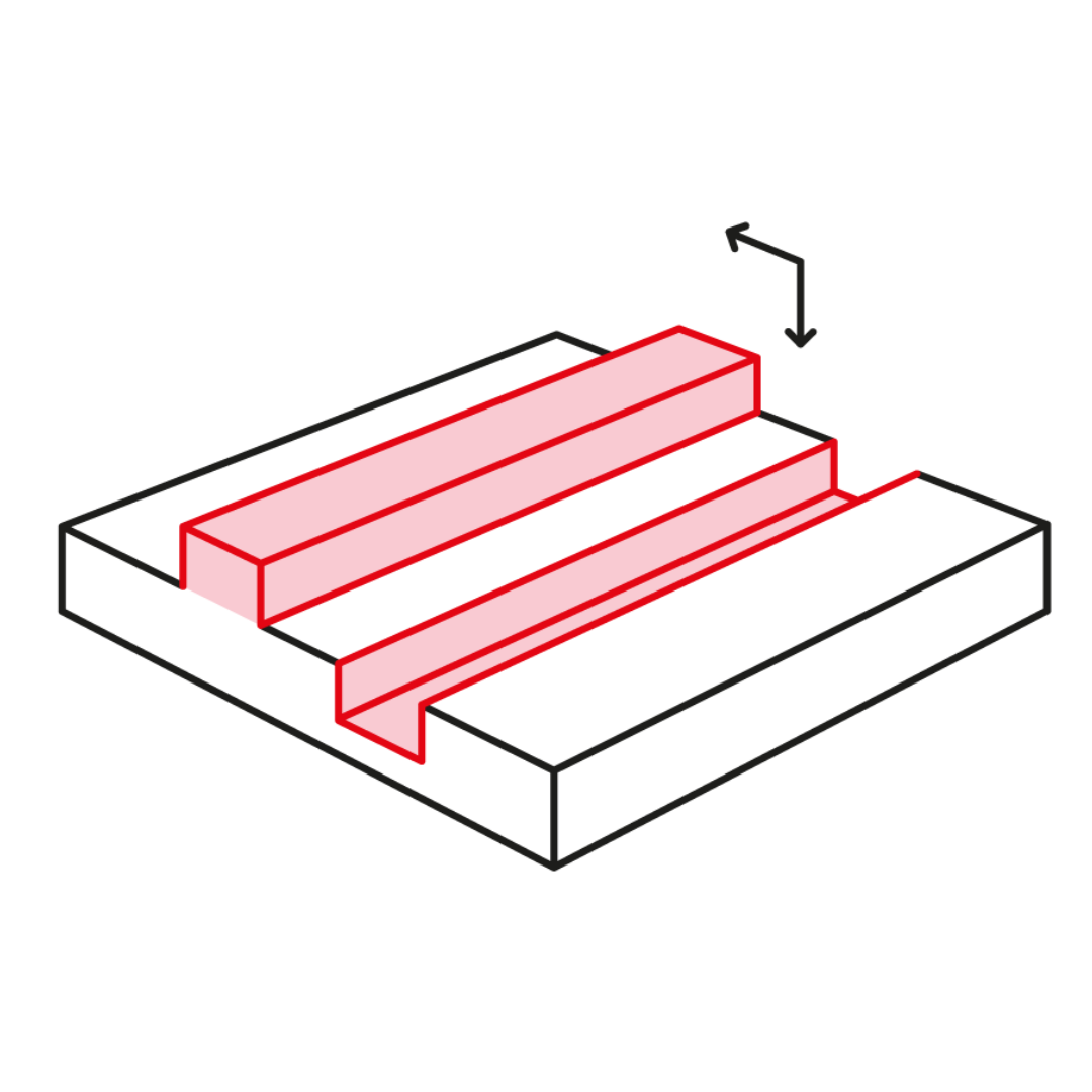
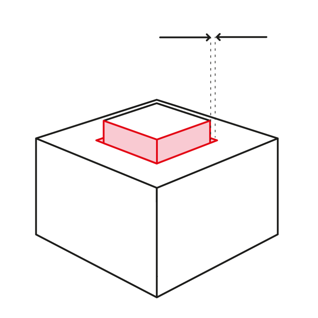
Embossed and engraved details
To ensure that embossed and engraved details are visible and functionally valid use at least 0,5 mm depth/height.
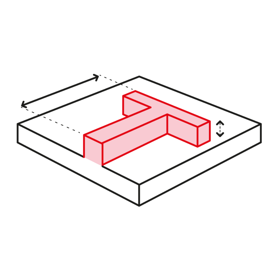
Feature size
For protruding features a minimum of 0.8 mm is recommended (etc. pins, bridges). For pattern features 0,3 mm is minimum repeatable dimension.
Sharp edges is required to rounded off. 0,4 mm or bigger radius is recommended.
Escape holes
To avoid deformities with SLS parts, it is recommended to use internal structures (etc. honeycomb) or alternatively chance parts hollow. This also has positive effect weight- and costwise. To remove unfused powder after printing phase, it is necessary to add escape holes. Adding at least two escape holes is recommended. Minimum diameter for the escape hole is 4 mm.
Tolerances
PA2200: ± 0,2 % (min. ±0,2 mm)
PA3200: ± 0,2 % (min. ±0,2 mm)
PA2241 FR: ± 0,2 % (min. ±0,2 mm)
PA2210 FR: ± 0,2 % (min. ±0,2 mm)
Alumide: ± 0,2 % (min. ±0,2 mm)
TPU: ± 0, 2% (min. ±0,3 mm)
PA11 ESD: ± 0,3 % (min. ±0,4 mm)
More accurate tolerances are possible with our validation process. Ask more from our engineers.
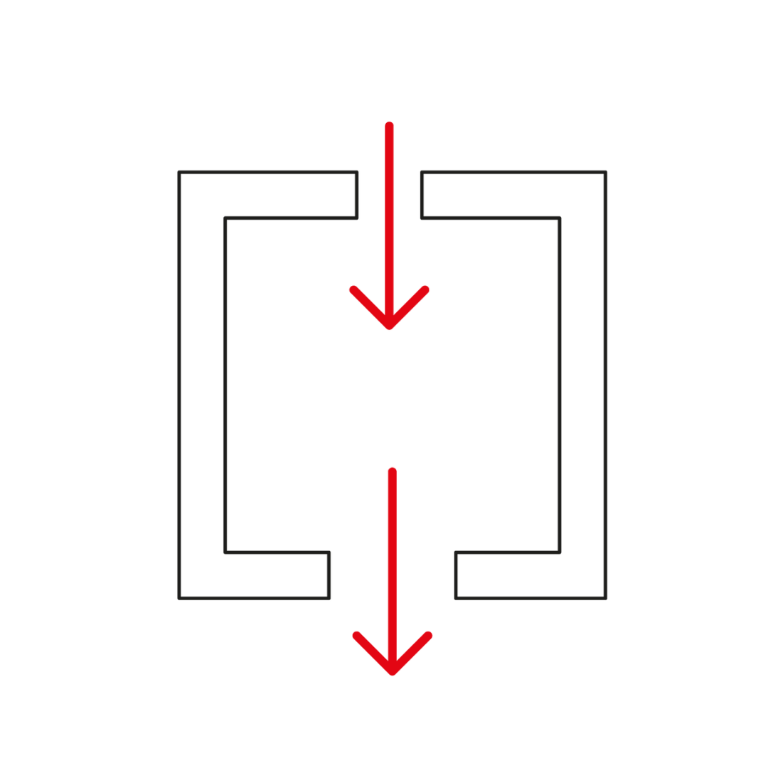
Clearance
Recommended clearance for fitting parts is 0,2 mm. Tight clearance can be done successfully with 0,1 mm clearance, but printing orientation needs to be determined for that. For interlocking and moving parts 0,5 mm clearance is recommended, so that unfused particles can be removed from the fitting area.
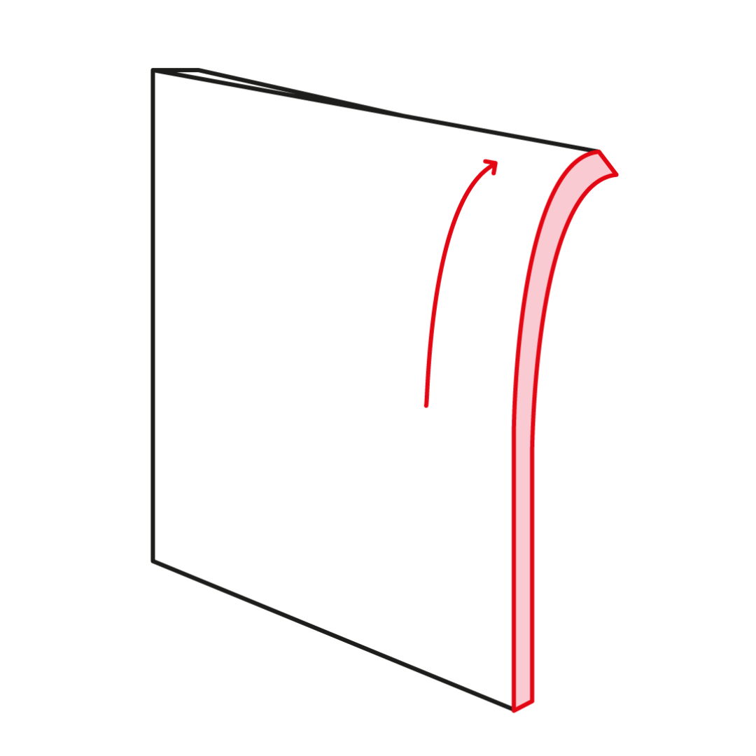
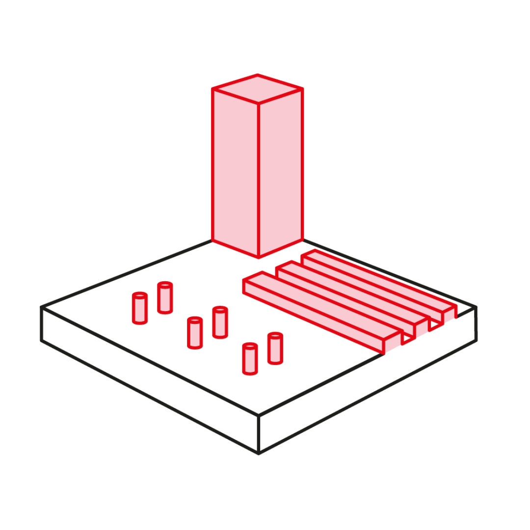
Warping
Large flat plane kind of parts have a high risk of warping. If possible, avoid wall thickness under 1mm if the flat area is relatively large. In case of boxes and frames add ribs and gussets to make structure more thickset.
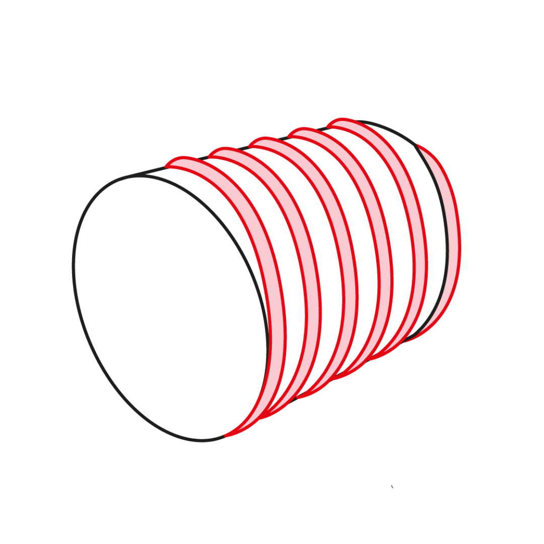
Threads
Threads can be designed directly into SLS print but there is still something to pay attention to. If the threads can be aligned perpendicularly to laser entry angle, thread sizes down to M5 are possible to execute with satisfying manor. Smaller threads than M5 are recommended to proceed by drilling, or threaded inserts.
Roughish surface of SLS print creates some friction between fitting component and threads. If this is causing problems, drilling or inserts are a better solution. A clearance of 0,1-0,2mm between outer and inner threads is recommended. If threads will face bigger forces or many times of twisting open and close, threaded inserts are recommended.
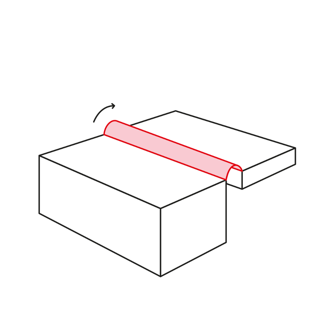
Living hinges
SLS is one of the only 3D-printing methods that can produce mechanically resistant living hinges. For the design of the hinge, thickness of 0,3-0,8 mm and minimum of 3 mm of lenght is recommended. Remember to add R 0,75-1,8 fillet to the joint between the living hinge and the part.
Annealing the living hinge after the printing phase is very important (E.g. immersing the part to boiling water and flexing the hinge by putting a rod in the middle of it).
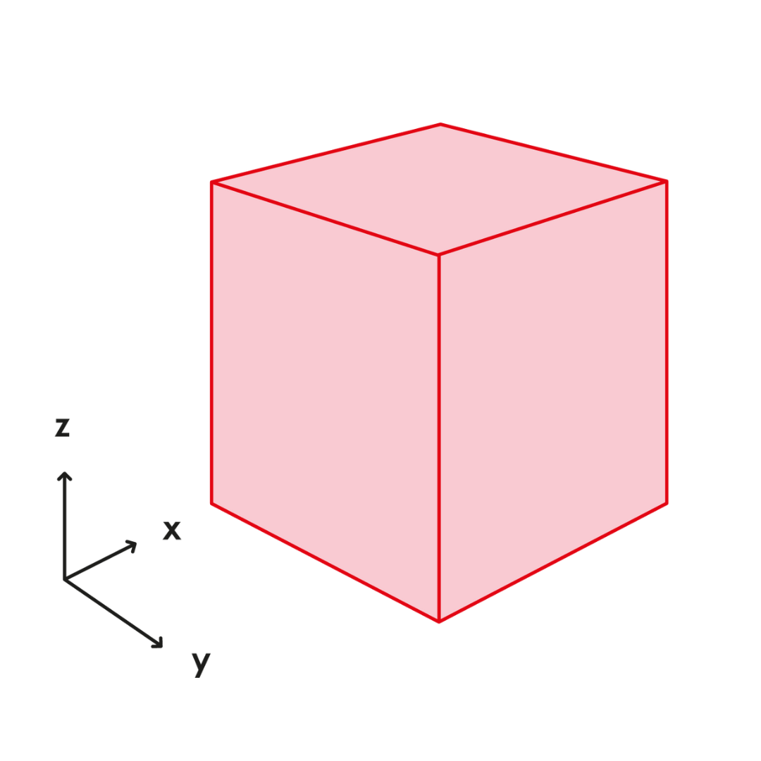
Product size
If the part is bigger than 320mm x 320mm x 600mm, it must be manufactured in parts. By adding joints (e.g. lap joint, jigsaw) parts can be printed separately and glued together afterwards. With good designing joints that are mechanically resistant and visually difficult to detect, are possible to be created.
Three reasons to invest in post-treatment for 3D printing
There is far too little talk about post-treatment of 3D prints. However, it not only makes the part or product better, it also helps it stand out from the competition in the market. As 3D printing is increasingly used in many companies, a basic level is no longer sufficient. As more and more printed parts are used as end products, their appearance, durability and features are becoming increasingly important. In this blog, we give you three reasons why you should use post-treatment.
Read more